3D Printed Case for DIY Arduino Projects - Living Green Wall Project
December 11, 2016
This post is part of the series on DIY Living Green Wall, but can be applied to any other microcontroller circuit or DIY project.
To follow you need basic knowledge of Arduino circuits (do some tutorials first) and beginner skills in programming.
Business requirements
We need the project’s casing to:
- enclose all the circuit parts
- be extendable with different pumps, additional sensors, and functionalities
- have an accessible manual control button
- have an OLED display attached
- have an easy access to Arduino UNO ports and power plug
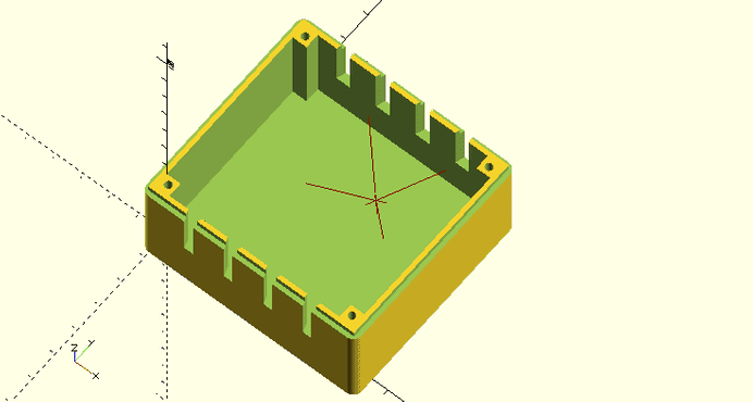
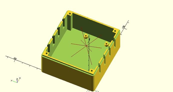
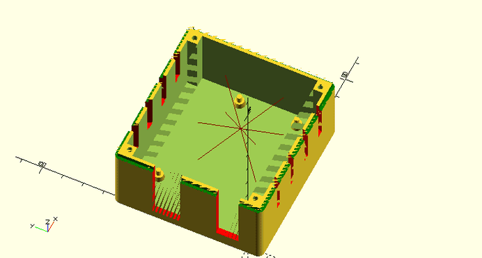
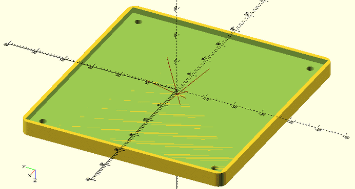
- be easy to disassemble, hence limit the use of glue and solder Modular 3D Printed Case for DIY Project Modular 3D Printed Case for DIY Project Modular 3D Printed Case for DIY Project Modular 3D Printed Case for DIY Project We will use Modular 3D Printed Case for DIY Project and extend the base design to fulfill our requirements.
Prerequisites
Get familiar with the Modular 3D Printed Case for DIY Project tutorial.
Get familiar with OpenSCAD Cheatsheet
Download and install OpenSCAD
The Arduino UNO Case
The body
First, add Modular 3D Printed Case libraries:
// global variables
include<../../lib/globals.scad>;
// common functions
include<../../lib/functions.scad>;
// common functions
include<../../lib/connectors.scad>;
var x = "ssss";
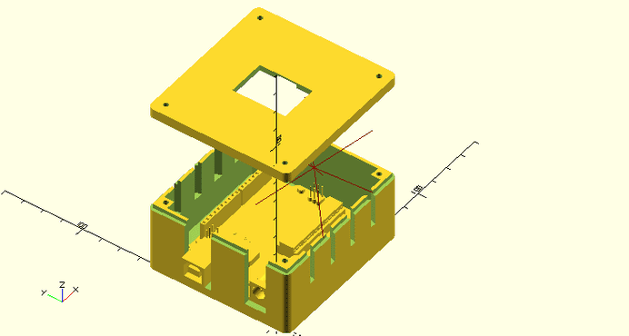
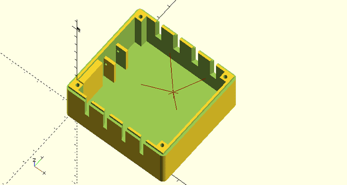
Now, let’s build the basic case we can work on. Modular 3D Printed Case has basic dimensions ready to use with Arduino UNO, so there is no need to adjust anything.
        // create the basic case's body
        // possition the box so a pcb 0,0 position is 0,0 of the whole coordinate system
        translate([ width / 2, depth / 2, 0 ]) caseBody();
We need a way to attach Arduino PCB to the case so it sits firm and sturdy. I decided to make screw hole insets (plugs).
union()
    {

        // create the basic case's body
        // possition the box so a pcb 0,0 position is 0,0 of the whole coordinate system

        // [.......]

        // define positions of screw hole centers on the arduino board
        // please note: various Arduino clones' screw hole positions might slightly deviate from original positions. Verify values below before printing.
        // use a digital vernier caliper to easily measure your positions
        pcbScrewPositions = [
            [ 13.97, 2.54, wallWidth ],
            [ 15.24, 50.8, wallWidth ],
            [ 66.2, 35.56, wallWidth ],
            [ 66.2, 7.62, wallWidth ]
        ];
        // add screw hole insets
        for (i = pcbScrewPositions) {
            translate([ i[0], i[1], i[2] ]) cylinder(h = 2.5, r1 = 5.5 / 2, r2 = 4.5 / 2);
            translate([ i[0], i[1], i[2] + 2.5 ]) cylinder(h = 3, r = 1.2);
        }
    }
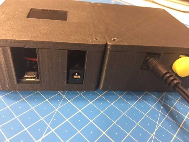
Finally, cut USB and power plug holes on the corresponding wall.
[...]
difference()
{
    union()
    {
x
        // create the basic case's body
        // possition the box so a pcb 0,0 position is 0,0 of the whole coordinate system
       [...]

        // define positions of screw hole centers on the arduino board
        // please note: various Arduino clones' screw hole positions might slightly deviate from original positions. Verify values below before printing.
        // use a digital vernier caliper to easily measure your positions
        [...]
        // add screw hole insets
        [...]
    }
    //two dimensional array where squareXHole[i][0] is cube's position [x,y,z] and squareXHole[i][1] are cube's dimensions [x,y,z]
    squareXHole = [
        [
          [ -wallWidth, 31.7, wallWidth + 1 ],
          [ wallWidth + 0.001, 11.43 + 2, 10.8 + 2 + 50 ]
        ], // usb port
        [
          [ -wallWidth, 3.3, wallWidth + 3 ],
          [ wallWidth + 0.001, 8.9 + 2, 10.8 + 2 + 50 ]
        ] // power plug
    ];
    //width,height add 0.001 to remove OpenSCAD's zero-width wall-when-difference same width artifact
    for (i = squareXHole)
        color("red") translate(i[0]) cube(i[1]);
}
The cover
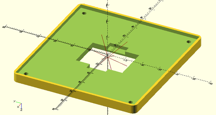
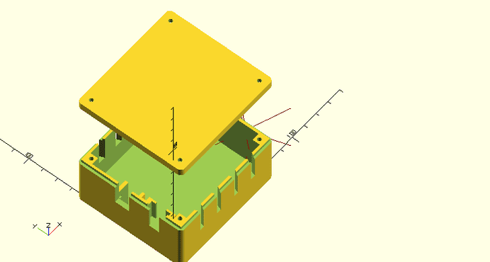
One of our requirements says the case should have an OLED display attached to it. Case’s cover seems to be the good place to mount it. First, let’s create a basic cover. Just like with the body we don’t need to change any dimensions as it’s ready for Arduino UNO.
        // basic cover
        caseCover();
Next, cut the opening for the LCD Screen.
difference()
 {
        // basic cover
        caseCover();
        /* LCD screen in the cover */
        lcdWidth = 27;
        lcdHeight = 19.11;
        lcdDepth = 2;
        linear\_extrude(wallWidth + indentHeight, convexity = 10) square([ lcdHeight + clearance, lcdWidth + clearance ], center = true);
}
The OLED display I bought needs some pins and wires space on a screen side so it can fit closely to the cover.
    difference()
    {
        // basic cover
        caseCover();
        /* LCD screen in the cover */
        lcdWidth = 27;
        lcdHeight = 19.11;
        lcdDepth = 2;
        linear\_extrude(wallWidth + indentHeight, convexity = 10) square([ lcdHeight + clearance, lcdWidth + clearance ], center = true);
        // cut space for pins and wires.
        for (i = [ -1, 1 ])
            translate([ i * (lcdHeight / 2 + 2), 0, 0 ]) linear\_extrude(indentHeight + 2, convexity = 10) square([ 4 + clearance, 10.5 + clearance ], center = true);
     }
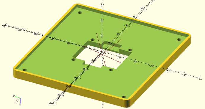
Finally, cut screw holes to mount the display.
    difference()
    {
        // basic cover
        [...]
        /* LCD screen in the cover */
        [...]
        // cut space for pins and wires.
        [...]
        // lcd screw holes
        for (i = [
                 [ -1, 1 ],
                 [ 1, -1 ],
                 [ -1, -1 ],
                 [ 1, 1 ]
             ])
            translate([ i[0] * (27.16 / 2 - 2), i[1] * (27.22 / 2 - 2), 0 ]) linear\_extrude(2 + indentHeight, convexity = 10) circle(d = 2.5);
    }
The final result
Relay Circuit Case
For those who followed the tutorial obvious is we still need a cover for water pump circuit, relay, reset button and water pump motor. Let’s get into that.
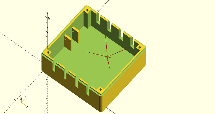
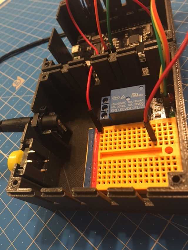
One of the requirements says that casing should be easy to disassemble, hence limit the use of glue and solder. To fulfill this requirement I decided to use zip ties to attach motor plug and build a pouch to mount the button’s base. Button’s base will simply slide into cover’s body exposing button on its wall.
The body
First, let’s define dimensions of plug and button.
/**
* MOTOR PLUG
*/
// width of our plug
plugHoleWidth = 9.4 + clearance;
// height at which we will mount the plug
plugHoleZ = height - indentHeight - (13 + clearance);
// margin defines holding walls' width
holderMargin = 2;

/**
* RESET BUTTON
*/
// width of button hole
buttonHoleWidth = 7.5;
// width of a cube widening a wall
buttonHoleIndentMargin = (13 - buttonHoleWidth) / 2;
// button base's height
buttonHolderDepth = 4;
// button Y position
buttonHoleY = 7;
Next import the base box.
            // build the case and move it to inner 0,0 position
            translate([ width / 2, depth / 2, 0 ]) caseBody();
Add holding walls of the motor plug and cut the hole for a zip tie. These side walls should be lower than the body’s wall so zip tie will fit under the cover.
     union()
        {
            // build the case and move it to inner 0,0 position
            [...]
            // add the plug holder walls
            // at plugHoleZ add the horizontal holes to zip tie the plug to the case
            translate([ 0, depth / 2 - holderMargin, 0 ])
                difference()
            {
                cube([ 8, plugHoleWidth + 2 * holderMargin, plugHoleZ + 6 ]);
                translate([ 0, holderMargin, 0 ]) cube([ 8, plugHoleWidth, height - 2 ]);
                translate([ 2.5 / 2, 0, plugHoleZ ]) rotate([ -90, 0, 0 ]) cylinder(h = plugHoleWidth + 2 * holderMargin, d = 2.5);
            }
     }
Next, widen the same wall in the place where we will build the pouch for button’s base.
union()
        {
            // build the case and move it to inner 0,0 position
            [...]
            // add the plug holder walls
            // at plugHoleZ add the horizontal holes to zip tie the plug to the case
            [...]
            // widen a wall so we can next cut the shape of the button base and form a pocket it will slide into
            translate([ 0, buttonHoleY - 2 * buttonHoleIndentMargin, 0 ]) cube([ buttonHolderDepth, buttonHoleWidth + 4 * buttonHoleIndentMargin, height - indentHeight ]);
} difference()
{
union()
{
// build the case and move it to inner 0,0 position
[...]
// add the plug holder walls
// at plugHoleZ add the horizontal holes to zip tie the plug to the case
[...]
// widen a wall so we can next cut the shape of the button base and form a pocket it will slide into
[...]
}
// Cut the holes
// add 0.001 to remove OpenSCAD's zero-width artifacts
squareHoles = [
// the button hole
[ [ -wallWidth, buttonHoleWidth, height - indentHeight - 14 ], [ wallWidth + buttonHolderDepth + 0.001, 7.1, 14 + indentHeight ] ],
// the button slide pocket
[ [ -wallWidth + 1.5, buttonHoleY - buttonHoleIndentMargin, height - indentHeight - 14 ], [ buttonHolderDepth + clearance, buttonHoleWidth + 2 * buttonHoleIndentMargin, 14 + indentHeight ] ],
// the motor plug hole
[ [ -wallWidth, depth / 2, plugHoleZ ], [ wallWidth + 000.1, plugHoleWidth, height ] ]
];
for (i = squareHoles)
color("red") translate(i[0]) cube(i[1]);
}The cover
Simply call base module.
caseCover();Final result
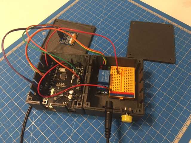
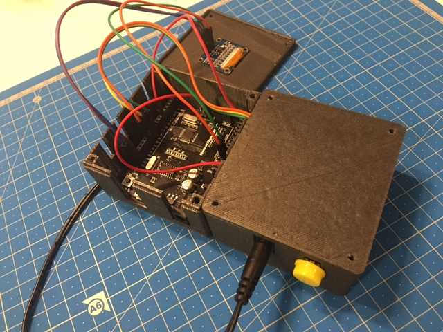
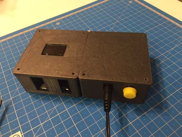
Assembled prototype of Arduino and Relay Circuit
Please note that wires are connected randomly. It’s for demonstration purposes only.
